


 8 / 221

THERMOSTATS
?
pages
127
TECHNICAL HELP
Connections....................................................................................See page 127
www.white-rodgers.com9
EASY INSTALL
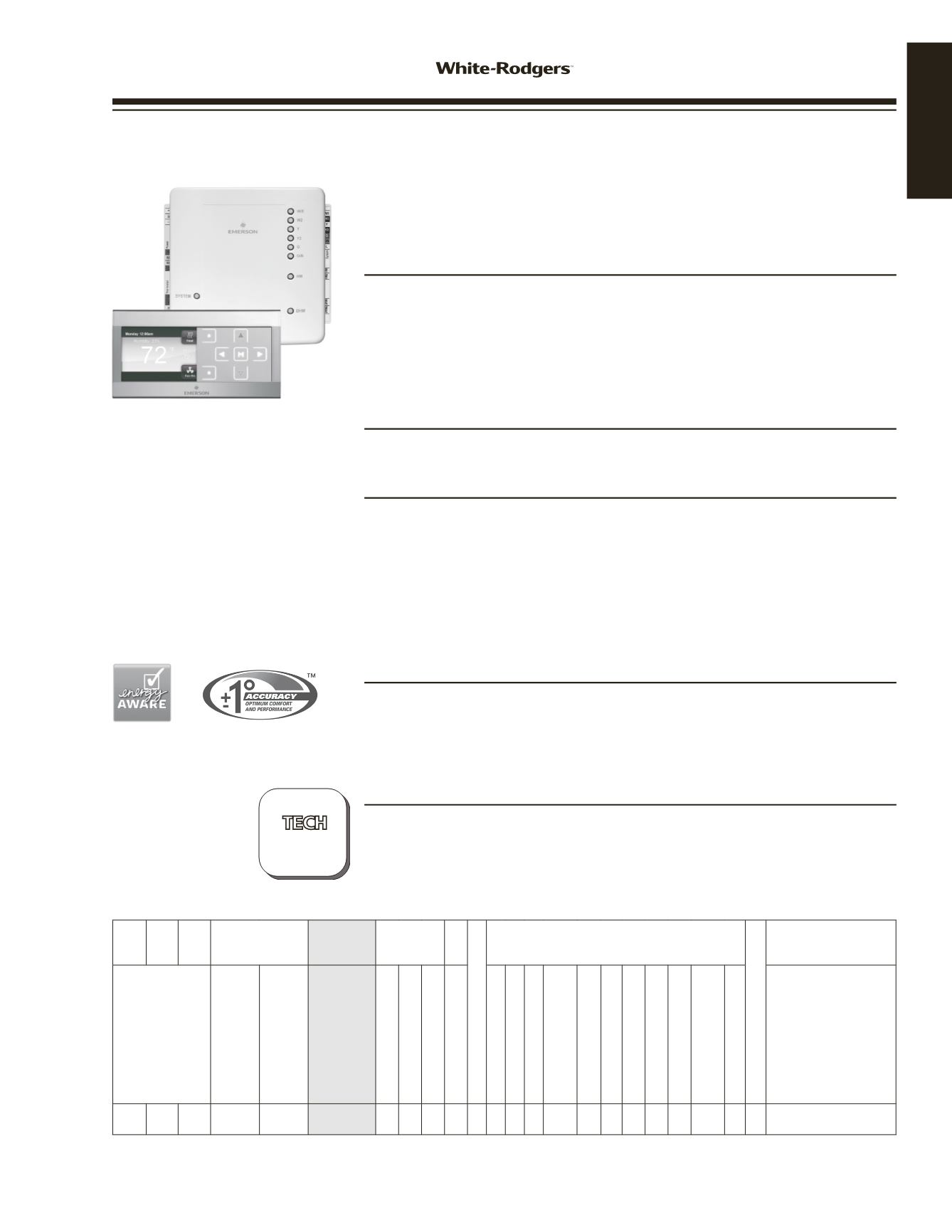
THERMOSTAT
1HDEZ-1521
Includes User Interface and
Equipment Control
Inspire
™
Universal 4-Wire Color
Thermostat System
Upgrade Single Stage Applications to Premium High-Efficiency
Systems (Staging, Heat Pump or Heat Pump with Dual Fuel) – Using
Existing 4 Wires
FEATURES
• Reusable plug-in configuration tool – eliminates multiple trips up and down stairs
during set up and system testing.
• USB port to quickly upload your favorite Installation Settings, Programs and
personalized Company Contact Information.
•
5
/
8
”
thin profile with vibrant color display.
• Color coded LEDs provide positive feedback for easy setup.
• Dehumidification, humidification.
DIMENSION
Interface ..................... 3
1
/
4
”
H x 6
1
/
8
”
W x
5
/
8
”
D
Control ........................ 5
1
/
2
”
H x 5
3
/
4
”
W x 1
1
/
2
”
D
SPECIFICATIONS
Electrical Rating:
Hardwire . . . . . . . . . . . . 20-30 VAC, NEC Class II 50/60Hz or DC
Terminal Load . . . . . . . . . . 1.5 A per terminal,
2.5 A maximum load (all terminals combined)
Setpoint Range . . . . . . . . . 45 to 99°F (7 to 37°C)
Rated Differential . . . . . . . . . Heat 0.6°F; Cool 1.2°F
Operating Ambient . . . . . . . . 32 to +105°F (0 to +41°C) – Interface
-30 to +150°F (-34 to 66°C) – Control
Operating Humidity Range . . . . . 90% non-condensing maximum
PARTS AND ACCESSORIES
See end of thermostats section for additional parts and accessories
• F4-1400 — Thermostat Plug-in Configuration Tool
• F145-1378 — Outdoor Remote Sensor
• F29-0198 — Locking Thermostat Guard - Clear Plastic
• F29-0220 — Locking Thermostat Guard - Metal, Solid Base
• F29-0222 — Locking Thermostat Guard - Metal, Ring Base
Inspire
™
Universal 4-Wire Color Thermostat System
24 VOLT
Single
Stage
Multi-
Stage
Heat
Pump
Programs
Model
Applications
Thermostat Power Source*
Selectable Performance Features
Display Size (Square inches)
Terminals
Stages Heat/Cool
by System
Program
Options
Periods
per day
Options
Model
Number
Gas / Oil / Electric
3 Wire Zone Valve
Millivolt Compatible
Humidity Control
(H)-Humidity / (D)-Dihumidity
Auto Changeover
Programmable Fan
Energy Aware
Comfort Alert®
A.C. System Protection
(P)-Passive/(A)-Active§
Dual Fuel Heat Pump Control
(L)-Logic/(O)-Outdoor Sensor
Dual Fuel Heat Stages HP/Gas
Aux. Heat Lockout with
Outdoor Sensor
Keypad Lockout
(T)-Total/(P)-Partial
Setpoint Temperature Limits
Adjustable Max./Min.
Indoor Remote Sensors
Max. Number + Thermostat
Average and/or Weighted
Remote Temperature Sensing
RC, RH, C, W/E, W2, Y,
Y2, O/B, G, L, +, S, -,
DHM, DHM2, HM, HM2,
R, 1, 2, C- Thermostat 1,
2, C, R
1/1 2/2 4/2 7, Ø 4, Ø
1HDEZ-1521
H,D H
A 0 ‡ 2/2
1 5.5
*H = Hardwired (Requires Common)
When used with an outdoor sensor provides options
to lock out auxiliary heat above selected outdoor
temperature.